
The ESP32 Sensor Lab is a small teaching rig: an ESP32-S3 reads an ultrasonic ranger, a light sensor, an IMU, and a TFT screen, drives a laser diode, and streams everything to a Flask dashboard in the browser. The goal was never just to get the sensors working — it was to build something that surfaces live power, timing, and interference problems as they happen, the same failures you'd hit on any real embedded project.
What follows is the current state of the hardware and software, and the debugging path that got it there. Most of the interesting parts of this project turned out to be the parts that didn't work at first.
The hardware
The core is an ESP32-S3-DevKitC-1, chosen for its dual I2C peripherals and generous free GPIO once the strapping pins, native-USB pins, and PSRAM-reserved pins are set aside. Four peripherals hang off it:
| Sensor | Interface | Pins | Notes |
|---|---|---|---|
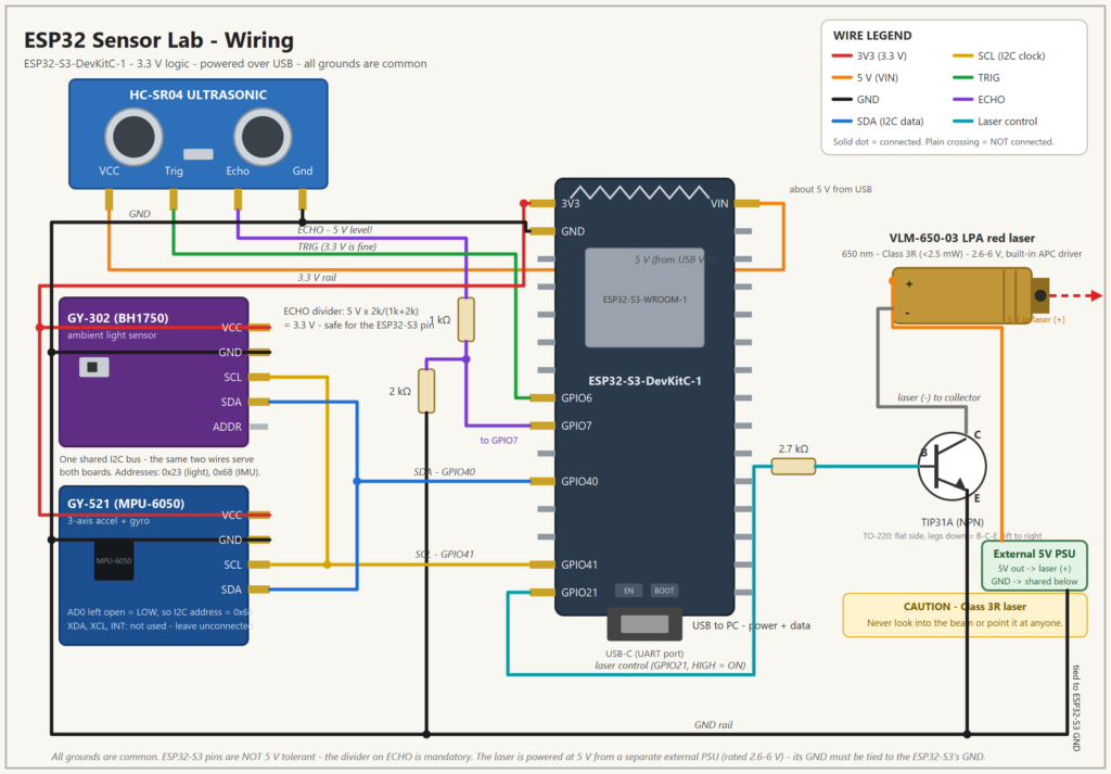
| HC-SR04 ultrasonic | Digital | TRIG 6, ECHO 7 | Echo is a 5 V output but ESP32-S3 pins are 3.3 V max, so ECHO goes through a voltage divider (ECHO → 1 kΩ → GPIO7 node → 2 kΩ → GND) that divides 5 V down to ~3.3 V. |
| BH1750 light sensor | I2C bus 0 | SDA 40, SCL 41 | Shares the bus with the IMU; auto-detected at boot. |
| MPU-6050 accel + gyro | I2C bus 0 | SDA 40, SCL 41 | Originally its own bus on GPIO 6/7/15 — moved after those pins turned out to be spoken for by other peripherals. |
| VLM-650-03 laser | Switched 5 V | GPIO 21 | Base drive to a TIP31A transistor via a 2.7 kΩ resistor. Powered from a separate external 5 V supply, not the ESP32's own rail — its ground is tied back to the ESP32-S3's GND. |
| ILI9341 TFT | SPI | CS 10, DC 8, RST 9 | Driven with a patched TFT_eSPI fork — stock 2.5.43 crashes on this chip. More on why below. |
Rather than dead-bugging all of this on a breadboard indefinitely, the sensors sit on a custom carrier PCB designed in KiCad, with dedicated sockets for each module so they can be swapped without resoldering. It's routed, DRC-clean, and exported as JLCPCB-ready Gerbers.
The dashboard
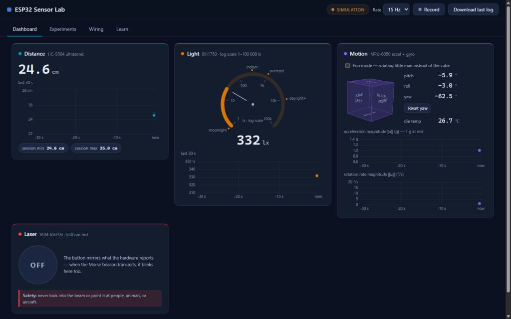
A small Flask server reads the ESP32's serial telemetry and republishes it to a single-page dashboard: live distance, lux, and IMU readouts, a rolling 30-second chart per sensor, and a CSS 3D cube that tracks the board's actual pitch, roll, and yaw in real time. A "fun mode" toggle swaps the cube for a little rotating figure — same transform, different divs underneath. No cloud, no accounts: everything stays on the machine it's plugged into.
The finished build
Here's the wiring as it stands today: the light sensor and IMU share one I2C bus on GPIO40/41, and the laser is switched from GPIO21 through a TIP31A transistor, powered from its own external 5 V supply with a shared ground back to the ESP32.
Next up: routing power properly onto the carrier PCB itself, so the external supply becomes part of the board rather than a bench accessory.
New: four more sensor games
The dashboard's Experiments tab just grew from four games to eight. Same architecture as before — vanilla JS, no libraries, still fully offline — just more ways to play with the sensors:
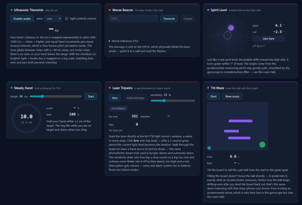
- Laser Tripwire — aim the laser at the light sensor and arm it; a broken beam latches a siren, just like a real photoelectric security alarm.
- Tilt Maze — a canvas ball game where tilt accelerates the ball rather than positioning it, so you feel accelerometer drift firsthand.
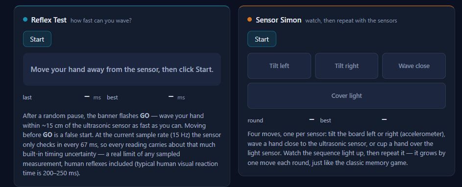
- Reflex Test — a reaction-time tester on the ultrasonic sensor, with a note on how sample rate limits timing precision.
- Sensor Simon — a Simon-Says memory game spanning three sensors at once: tilt, wave, and cover-the-light-sensor.
Recent Comments