
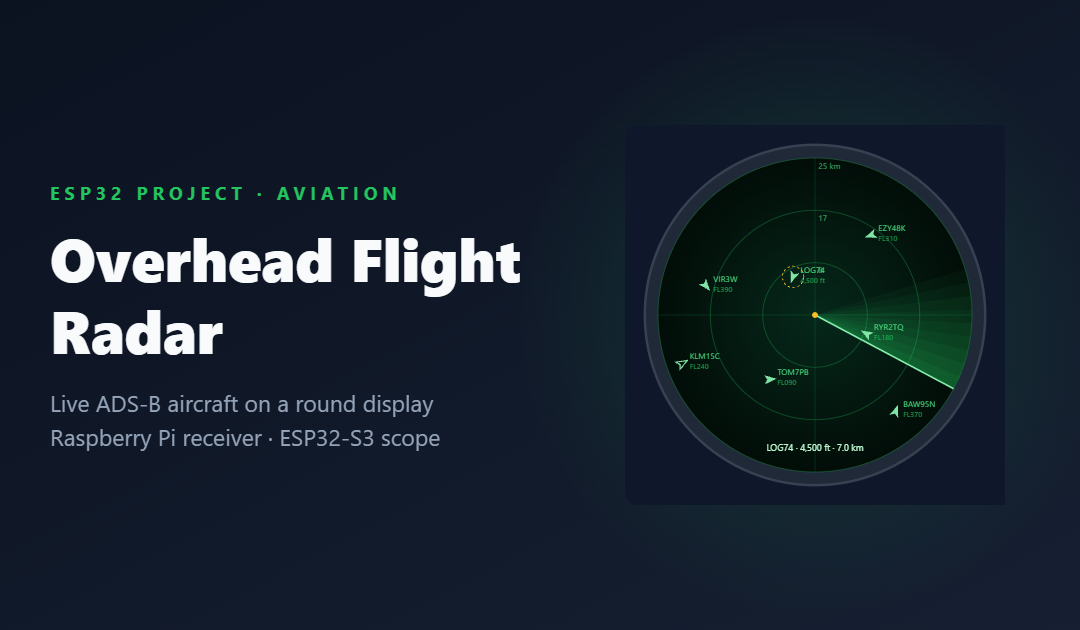
Look up on a clear day almost anywhere in the UK and there is a good chance an airliner is crossing the sky. Every one of them is broadcasting its position, altitude, speed and callsign several times a second on 1090 MHz, and with under £100 of hardware you can listen in. This project turns that stream into a desk ornament: a small round screen that works like an old radar scope, with a sweeping beam and a blip for every aircraft within range.
Where the project is today: design stage. This post sets out the complete design: hardware, wiring, software and how it will be tested. Nothing here has been built and tested yet, and the code samples are design sketches, labelled as such.
How aircraft tell everyone where they are
ADS-B (Automatic Dependent Surveillance–Broadcast) is not radar in the traditional sense. Nothing on the ground bounces a signal off the aircraft. Instead, each aircraft works out its own position from satellite navigation and broadcasts it, with altitude, ground speed, track and identity, as short digital messages on 1090 MHz. Air traffic control and other aircraft use these broadcasts, and because they are not encrypted, anyone with a suitable receiver can hear them too.
Each message lasts 120 microseconds: an 8 µs preamble followed by 112 bits of data at one megabit per second, using pulse-position modulation. Decoding that needs a receiver sampling millions of times a second plus serious signal processing. A cheap software-defined radio (SDR) dongle and a Raspberry Pi are good at exactly that, and an ESP32 is not.
So the design splits the job. The Pi listens and decodes; the ESP32 does what it is best at, running a responsive, low-power display on the desk.
The hardware
| Part | Why this one | Approx. £ |
|---|---|---|
| Raspberry Pi Zero 2 W | Runs the decoder. Any Pi 3, 4 or 5 also works; one SDR barely troubles a Zero 2 W. | 15–20 |
| FlightAware Pro Stick Plus | RTL-SDR dongle with a built-in 1090 MHz filter and amplifier. An RTL-SDR Blog V4 also works. | 30–40 |
| 1090 MHz antenna | Home-made quarter-wave ground plane for pennies, or a commercial collinear for more range. | 5–60 |
| ESP32-S3-DevKitC-1 (N16R8) | Dual-core with Wi-Fi, plus 8 MB PSRAM for comfortable JSON parsing and a full-screen frame buffer. | 12–18 |
| 1.28" GC9A01 round display | 240 × 240 IPS. Round glass makes a radar look right, and SPI means only six signal wires. | 5–10 |
| EC11 rotary encoder with push switch | Turn to change range, press to select the next aircraft. | 2–4 |
| Power supplies, Pi microSD card | USB-C 5 V for both halves, plus a card for the Pi’s operating system. | 10–15 |
| PETG filament, M2.5 screws | A printed "radar console" enclosure. | 3–5 |
Antenna first
Range is mostly about the antenna and how high it is. A simple quarter-wave ground plane, with elements 69 mm long (a quarter of the 275 mm wavelength at 1090 MHz), in a loft or high window will typically hear aircraft tens of miles away, and a proper collinear on the roof can reach much further. The display only needs the nearest 50 km or so, so a modest antenna is fine. A filtered dongle such as the Pro Stick Plus helps in towns, where strong mobile phone signals can swamp a cheap receiver.
Wiring
The display and encoder connect to an ESP32-S3-DevKitC-1 as shown below. These pins are a proposal: they avoid the S3's strapping pins (0, 3, 45 and 46), the USB pins (19 and 20) and the pins used by the module's flash and octal PSRAM (26–32 and 35–37). Check them against your exact board before soldering.
The encoder's common pin and the other side of its push switch go to ground; the ESP32's internal pull-ups handle the rest. The backlight pin uses PWM, so the screen can dim itself at night.
Software on the Pi: readsb and tar1090
The Pi runs readsb, an actively maintained ADS-B decoder, and tar1090, a web map with a handy side effect: it publishes every aircraft the receiver can hear as a JSON file, refreshed every second. Both are open source and installed with their author's scripts (check each project's README for the current instructions):
# Decoder (readsb), using wiedehopf's install script
sudo bash -c "$(wget -O - https://github.com/wiedehopf/adsb-scripts/raw/master/readsb-install.sh)"

# Web map (tar1090), which also serves the JSON the ESP32 reads
sudo bash -c "$(wget -nv -O - https://github.com/wiedehopf/tar1090/raw/master/install.sh)"

# Check the feed from any PC on the network
curl http://PI-ADDRESS/tar1090/data/aircraft.json
Each entry in aircraft.json carries what the display needs: hex (the aircraft's unique 24-bit ICAO address), flight (callsign, padded with spaces), lat and lon, alt_baro (feet, or the word "ground"), gs (ground speed in knots), track (degrees) and seen_pos (seconds since the last position). Not every aircraft sends every field. Some only report altitude, which still counts towards a "heard but not plotted" total.
Software on the ESP32
The firmware uses the Arduino core for ESP32 with three well-proven libraries: LovyanGFX for fast SPI drawing into an off-screen sprite (so nothing flickers), ArduinoJson with a filter so only the needed fields are kept in memory, and the standard HTTPClient for the request. The JSON is parsed straight from the network stream rather than downloaded first, which matters on a busy summer afternoon when the file can grow past a hundred kilobytes. Work is split into FreeRTOS tasks, so a slow Wi-Fi request never stutters the sweep animation.
| Task | Job | Rate |
|---|---|---|
| fetch | HTTP GET aircraft.json, filter, parse into a fresh aircraft table | 1 Hz |
| model | Merge updates, mark aircraft stale after 10 s, drop them after 60 s, sort by distance | 1 Hz |
| render | Draw rings, sweep, blips and labels into a sprite, then push it to the screen | ~30 fps |
| input | Read the encoder: range 10, 25, 50 or 100 km; press to select the next aircraft | on event |
| net | Keep Wi-Fi connected, back off on failures, show NO DATA in amber if the feed goes stale | on event |
From latitude and longitude to pixels
Within 100 km, the Earth is flat enough for a simple equirectangular projection around the home position. Using the mean latitude of the two points keeps the east–west scale honest, and the result maps straight onto the round screen:
// Design sketch - NOT TESTED ON HARDWARE.
constexpr float EARTH_R_KM = 6371.0f;
constexpr float DEG_TO_RAD = 0.01745329252f;

// East/north offset in km of an aircraft from home (fine at these ranges)
void toLocalKm(float lat, float lon, float homeLat, float homeLon, float &east, float &north) {
    const float meanLat = (lat + homeLat) * 0.5f * DEG_TO_RAD;
    east  = (lon - homeLon) * DEG_TO_RAD * cosf(meanLat) * EARTH_R_KM;
    north = (lat - homeLat) * DEG_TO_RAD * EARTH_R_KM;
}

// Map to the 240 x 240 round screen; false if outside the selected range
bool toScreen(float east, float north, float rangeKm, int &x, int &y) {
    constexpr int CX = 120, CY = 120, R = 112;     // leave a margin for the bezel
    if (east * east + north * north > rangeKm * rangeKm) return false;
    x = CX + int(east  / rangeKm * R);
    y = CY - int(north / rangeKm * R);             // screen y grows downwards
    return true;
}
The sweep is theatre, and that is fine
A real radar only "sees" a target when its beam points at it, which is why blips flare and fade on an old scope. ADS-B positions arrive continuously, so the sweep here is purely decorative: each blip brightens as the beam passes its bearing and slowly dims, just like the real thing, while its position keeps updating underneath. An aircraft that stops reporting is drawn hollow after ten seconds and removed after a minute, so it is always obvious when data is old rather than live.
Testing plan
- Replay first: record a few hours of
aircraft.jsonsnapshots on the Pi and serve them from a PC, so the display can be developed at the desk with repeatable data. - Cross-check positions: compare the blips with the tar1090 map in a browser at the same moment. Bearings and distances should agree to within a pixel or two.
- Edge cases: aircraft on the ground, missing callsigns, altitude-only aircraft, an empty sky at 3 a.m. and a crowded summer afternoon.
- Failure modes: Pi rebooted, Wi-Fi down, JSON cut off mid-transfer. The screen must say NO DATA rather than freeze with stale blips.
- Endurance: log frame rate, parse time and free memory over a 24-hour run to catch leaks.
Risks and limitations
- Range depends on the antenna and local terrain; a loft installation will miss low aircraft behind hills.
- Not every aircraft broadcasts ADS-B, and some light aircraft only report altitude, so the scope will never show everything in the sky.
- Busy airspace means big JSON files; the filter and streaming parse are there to keep memory under control, and will be tested against a worst case.
- This is a hobby display, not a navigation or safety tool.
What's next
The first build step is the Pi receiver, because it is useful on its own: tar1090's map is a great way to judge antenna placement. Then the ESP32 display, starting from replayed data. Later ideas include a gentle chime for low-flying aircraft, aircraft-type icons, and a second mode that lists the nearest five flights like an airport departures board.
If you enjoyed this, my ESP32-S3 vehicle computer design applies the same honesty-first thinking to GPS data.
Related articles
 Electronics & ESP32
Designing a Battery-Powered E-Paper Market Dashboard with the ESP32-S3
A picture-frame display that shows a watchlist and the day's market moves, wakes every 15 minutes during trading hours and sleeps the rest of the time. Hardware list, wiring, power budget, software design and test plan.
 Electronics & ESP32
Tap a Card, Hear a Story: Designing a Screen-Free ESP32-S3 Story Box
A battery-powered story player for children: place a picture card on the lid and the matching story plays from a microSD card. NFC, I2S audio, deep sleep and a parent mode, with the full hardware list, wiring and software design.
 Electronics & ESP32
Designing an ESP32-S3 Smart Vehicle Computer: GPS Trip Stats, Cabin Sensors and iPhone Music over Bluetooth LE
A 3.5-inch ESP32-S3 dashboard for the car: honest GPS speed, journey statistics, cabin climate and iPhone track info over Bluetooth LE. Here is the design, the traps already found, and the plan to build it properly.