
Plenty of cars, especially older ones, have no trip computer at all. The ones that do rarely show the things I actually want to glance at: an honest speed, how far this journey has been, how long it has taken, how warm the cabin is, and what is playing on my phone.
So the next project on the bench is a small auxiliary dashboard: a 3.5-inch colour touchscreen built around an ESP32-S3, with its own satellite receiver, a cabin climate sensor, journey logging to a microSD card and Bluetooth track information from an iPhone.
The rule for this one is simple. It has to be a real, buildable device, not a pretty mockup or a demo that only works on a desk. Every pin assignment comes from a schematic, every claim about a chip comes from its datasheet, and anything not yet tested on real hardware gets labelled that way.
Where the project is today: Phase 1, feasibility and design. This post is the design write-up: the parts, the reasoning, the traps I have already found and the plan for building and testing it. Nothing below has been validated on hardware yet, and I will say so wherever it matters. Later posts will follow the build.
This is an auxiliary information display. It is not, and never will be, a replacement for the car's speedometer or any other safety-critical instrument.
What it will show
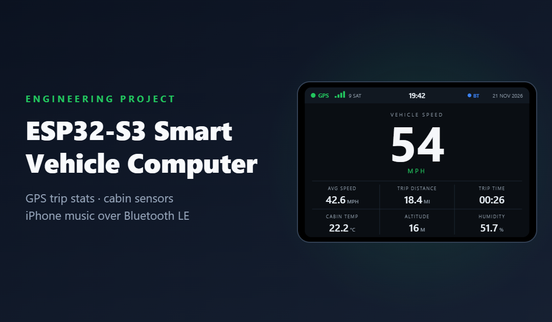
The main screen is designed for a two-second glance: one huge number, six supporting figures and status lights you can read from the corner of your eye. Here is the working layout at the screen's native 480 × 320 landscape resolution.
Everything else lives on secondary screens, meant for when the car is parked:
- Journey: distance, total and moving time, stopped time, moving average, maximum validated speed, and start time and place.
- Location: latitude, longitude, altitude, satellites in use, fix type, estimated accuracy, and UTC and local time.
- Environment: cabin temperature and humidity, the journey's minimum and maximum, and sensor health.
- Music: track, artist, playback state, plus play/pause, next and previous buttons.
- Settings: brightness, day/night theme, units, time zone, Bluetooth pairing, diagnostics, trip reset, storage status and firmware version.
The key design rule is that the device must work with no phone, no Wi-Fi and no mobile data. Satellites and a sensor are all it needs. The phone link is a bonus, never a dependency.
The hardware, and why each part earned its place
| Part | Why this one | Role |
|---|---|---|
| Waveshare ESP32-S3-Touch-LCD-3.5 | A dual-core ESP32-S3 with 8 MB PSRAM and 16 MB flash, a 3.5-inch 320 × 480 IPS panel (ST7796 controller) with FT6336 capacitive touch, a microSD slot, RTC, six-axis IMU and USB-C, all on one board. Fewer wires in a car means fewer things to rattle loose. | Brain + display |
| SparkFun MAX-M10S breakout | A u-blox M10 receiver that can track GPS, Galileo, GLONASS and BeiDou concurrently, with low power draw, an external antenna connection and a UART interface. Crucially, it reports ground speed directly (more on why below). | GNSS receiver |
| Active GNSS antenna | Lets the receiver sit inside the enclosure while the antenna sees the sky through the windscreen. | Sky view |
| Sensirion SHT31 breakout | A proven, factory-calibrated I2C sensor (address 0x44 or 0x45) that sends a checksum with every reading, so corrupted data can be spotted and rejected. | Cabin climate |
| Automotive DC-DC converter | A fused, ignition-switched, protected 12 V to 5 V supply. A car’s electrical system is hostile; more on that below. | Power |
The first trap: two boards with almost the same name
Waveshare also sells a "3.5B" version of this board. It looks very similar but is driven differently, so drivers and examples written for one will not simply work on the other. The first Phase 1 task is to confirm the exact board and PCB revision on the bench, then build every GPIO assignment from the official schematic for that revision. No pins get allocated from memory, a forum post or a pinout image of a "similar" board.
This matters more than usual here, because the board already uses many of its pins for the display, touch, SD card, RTC and IMU. The GNSS serial link and the SHT31 need pins that are genuinely free. The SHT31 may be able to share the board's existing I2C bus with the touch controller and RTC, but only if the addresses do not clash and the pull-up resistors are right. A full resource-allocation table comes before a single wire is soldered.
How it all connects
Electrically, the design is simple: one protected 5 V feed, a UART link to the GNSS module, an I2C link to the sensor pod and an optional ignition-sense input. The drawing shows the signals only. The actual GPIO numbers will come from the schematic review, not from guesswork.
Bill of materials (approximate UK prices)
| Item | Notes | Approx. £ |
|---|---|---|
| Waveshare ESP32-S3-Touch-LCD-3.5 | Original ST7796 version, not the 3.5B | 25–35 |
| SparkFun MAX-M10S GNSS breakout | u-blox M10, 3.3 V, UART and Qwiic | 40–50 |
| Active GNSS antenna | Windscreen-mounted, with the right connector or adapter | 10–20 |
| SHT31 breakout | Remote-mounted in the vented sensor pod | 5–15 |
| Automotive 12 V → 5 V converter | Protected and rated for vehicle use | 15–30 |
| Add-a-fuse tap, inline fuse, cable | Ignition-switched feed | 5–10 |
| High-endurance microSD card | 16–32 GB, FAT32 | 8–15 |
| PETG or ASA filament | About 150 g for the enclosure | 3–5 |
| Leads, connectors, screws, heat-shrink | JST/Qwiic leads, M2.5 hardware | ~10 |
Prices are rough November 2026 figures and vary between suppliers, so treat the total as a ballpark rather than a quote: the essentials come to roughly £120 to £190.
The Bluetooth surprise
The obvious way to show track names in a car is AVRCP, the Bluetooth profile car stereos use. The catch: AVRCP runs over Bluetooth Classic, and the ESP32-S3 only has Bluetooth Low Energy. Any design that quietly assumed Classic Bluetooth would fall over the moment it met real hardware.
So phone integration splits by platform.
iPhone: Apple Media Service
iOS offers the Apple Media Service (AMS), a documented BLE service (UUID 89D3502B-0F36-433A-8EF4-C502AD55F8DC) that lets an accessory see what is playing and send remote commands. It has three parts:
- Remote Command: send play, pause, next track, previous track and similar commands. The iPhone also reports which commands the current app supports.
- Entity Update: subscribe to the attributes you care about, such as track title, artist and playback state, and get notified when they change.
- Entity Attribute: read the full value of an attribute when the notified version was truncated to fit in a Bluetooth packet.
The dashboard acts as the Bluetooth client and the iPhone as the server, which feels backwards but is how Apple designed it. The connection has to be paired and encrypted before AMS appears. Music keeps playing through the car's own stereo: this is purely a "now playing" display and remote control.
Things I am deliberately not assuming: that every app (Apple Music, Spotify, podcasts) behaves the same, that long titles arrive in full, or that commands work identically on every iOS version. Step one is a tiny proof of concept that reads one track title and sends one play/pause command. The full music screen only gets built once that works on a real iPhone.
Android: a companion app
Android has no equivalent of AMS. The plan there is a small Kotlin companion app that reads the active media session (with the user's permission), sends track details to the dashboard over BLE and relays button presses back. It is a stretch goal, and the core device does not depend on it.
Making GPS speed honest
The hardest part of this project is not the graphics. It is deciding when the speed on screen is true. A GPS module will happily hand you a number in a multi-storey car park, in a tunnel or in the first seconds after power-on. A display that shows "0 mph" when it really means "I have no idea" is worse than useless.
So speed is driven by an explicit set of states, and each one looks different on screen:
| State | Meaning and display | Status light |
|---|---|---|
| No receiver | No data arriving from the GNSS module at all. Speed shown as dashes, with “NO RECEIVER”. | Red |
| Acquiring | Searching for satellites, no usable fix yet. Speed shown as dashes, satellite count visible. | Amber |
| Stale | Had a fix, but fresh updates have stopped. Speed shown as dashes until good data returns. | Amber → red |
| Stationary | Valid fix, vehicle not moving. Speed reads 0. | Green |
| Moving | Valid fix, vehicle moving. Live speed. | Green |
To make those states concrete, here is a simulated twelve-second journey: acquiring satellites, sitting still, pulling away, losing the signal in a tunnel and recovering on the other side.
Here is how "signal lost" differs from a parked car. Trip totals and averages are preserved, distance stops accumulating, and the last known position is kept but clearly marked as historical.
Speed from Doppler, not from dots on a map
The naive way to get speed is to take two positions, measure the distance between them and divide by the time. Position noise of a few metres makes that jumpy, especially at low speed. A u-blox receiver instead measures velocity from the Doppler shift of the satellite signals, which is far smoother. The firmware uses the receiver's own ground speed as its primary source and converts it to UK units once:
mph = km/h × 0.6213711922The parked-car problem
Leave a GPS receiver on a driveway and it will report a slowly wandering position and small, non-zero speeds. Shown raw, the dashboard would read "1 mph" while parked and the trip distance would creep up all night. The fix is hysteresis: a higher threshold to start moving than to stop, plus a minimum duration. Here is a design sketch of that logic:
// Design sketch - NOT TESTED ON HARDWARE. Thresholds are starting points to tune.
constexpr float    KMH_TO_MPH       = 0.6213711922f;
constexpr float    START_MOVING_MPH = 2.0f;   // must rise above this...
constexpr float    STOP_MOVING_MPH  = 1.0f;   // ...and fall below this to stop
constexpr uint32_t START_HOLD_MS    = 2000;   // for at least this long
constexpr uint32_t STALE_AFTER_MS   = 2000;   // no fresh fix means stale

MotionState classify(const GnssSample &s, MotionState prev, uint32_t now_ms) {
    if (!s.receiver_alive)                        return MotionState::NoReceiver;
    if (!s.fix_valid)                             return MotionState::Acquiring;
    if (now_ms - s.fix_time_ms > STALE_AFTER_MS)  return MotionState::Stale;

    const float mph = s.ground_speed_kmh * KMH_TO_MPH;
    if (prev == MotionState::Moving)
        return (mph < STOP_MOVING_MPH) ? MotionState::Stationary : MotionState::Moving;

    return (mph > START_MOVING_MPH && s.ms_above_start >= START_HOLD_MS)
               ? MotionState::Moving
               : MotionState::Stationary;
}
On top of that, samples are rejected if they imply impossible behaviour, such as an acceleration no road car can manage or a position jump of hundreds of metres in one second (a classic multipath error near tall buildings). The receiver's own accuracy estimates and satellite count act as quality gates. All of these thresholds live in a configuration file rather than in the code, because they will be tuned with real driving data.
Defining the numbers properly
"Average speed" sounds obvious until you ask whether the time spent sitting at traffic lights counts. The trip computer defines every figure explicitly:
| Figure | Definition | Calculation |
|---|---|---|
| Trip distance | Sum of validated distance increments. Nothing is added while stationary, stale or without a fix. | Σ validated Δd |
| Journey time | Clock time since the trip started, excluding any pauses. | now − start − pauses |
| Moving time | Time spent in the Moving state. | Σ moving Δt |
| Overall average | Includes time spent stopped at lights and junctions. | distance ÷ journey time |
| Moving average | Ignores time spent stationary. | distance ÷ moving time |
| Maximum speed | The highest speed that passed validation, not the highest raw reading. | max(validated speed) |
Both averages show dashes until there is enough time to divide by, so there is never a divide-by-zero or a silly 900 mph average in the first second.
For distance there are two candidate methods: integrate the validated speed over time, or add up the distances between successive validated positions. Speed integration is smooth but can drift; position summing is anchored to the map but noisy. The plan is to log both on real journeys, compare them with a measured route and the car's own odometer, and choose (or blend) based on evidence rather than preference.
Getting the time right
Satellites provide very accurate UTC, but UTC is not UK local time for half the year. The device keeps its clock in UTC and applies the Europe/London rule using the POSIX time-zone string GMT0BST,M3.5.0/1,M10.5.0: British Summer Time starts at 01:00 UTC on the last Sunday in March and ends on the last Sunday in October. The board's RTC keeps time when there is no satellite fix, and the clock shows a small "unsynced" marker until satellite time has been confirmed.
Car power is hostile
It is tempting to grab a cheap 12 V to 5 V converter and call it done, but a car's "12 V" is anything but steady. It sags well below that while the engine cranks, it carries spikes and noise from the alternator and motors, and a load dump (the battery connection dropping while the alternator is charging) can cause a large, sustained surge. Automotive standards such as ISO 7637-2 and ISO 16750-2 exist precisely because of this.
So there are two power designs:
- Bench prototype: a regulated USB-C 5 V supply. Nothing clever.
- Permanent installation: an ignition-switched, fused feed (via an add-a-fuse tap) into an automotive-rated 12 V to 5 V converter with reverse-polarity and transient protection, then into the board. Raw 12 V never touches the ESP32 board.
An optional ignition-sense line, through a voltage divider or opto-isolator, tells the firmware when the key turns off. With a small energy reserve, it can then save the trip and close its files cleanly before the power disappears, instead of hoping the SD card survived.
Logging without losing data
The microSD card holds the graphics, configuration, a summary of every journey and optional detailed logs, in a simple layout:
/smartcar/
    /assets/
        /icons/
        /backgrounds/
    /config/
    /trips/
    /exports/
    /logs/
Detailed records capture UTC time, position, altitude, speed, distance, satellite count, fix quality, temperature and humidity at a configurable interval. A Python tool on the PC turns them into CSV for spreadsheets and GPX for mapping software.
A few rules keep the data safe. Writes are buffered and flushed on a schedule rather than every second, which is kinder to the card. The in-progress trip is checkpointed to the ESP32's non-volatile storage, so a power cut does not lose the journey. And the dashboard keeps working normally with no card inserted at all. Missing, full and corrupted cards are all on the test list.
Software architecture
The firmware is written in C++ on Espressif's ESP-IDF framework, using LVGL for the graphics and FreeRTOS tasks to keep everything responsive. Each subsystem is a separate component with a clean interface, so the real receiver can be swapped for a simulated one on a PC.
The most important rule is hidden in the arrows: slow things never block fast things. An SD card that takes a moment to write, or a Bluetooth reconnection that is backing off, must never freeze the speed display. Tasks talk through message queues, the screen only redraws widgets whose values have actually changed (which avoids flicker), and a watchdog restarts anything that hangs.
A desktop simulator feeds synthetic journeys, including accelerating, cruising, stopping and driving into a tunnel, into the same trip logic, with unit tests for every calculation. It is a development tool, not proof: a simulator passing its tests says nothing about whether the hardware works.
The enclosure
The case will be 3D printed and designed parametrically, so the dimensions can change once the real board is under the calipers. Two decisions are already made:
- Not PLA. PLA starts to soften at around 60 °C, and a dashboard in summer sun can get hotter than that. PETG is the minimum; ASA is better for heat and UV.
- The sensor lives outside the hot zone. An SHT31 sitting next to the processor and display backlight measures the electronics, not the cabin. It goes in a small ventilated pod, separated from the main board, and its readings will be checked against a reference thermometer before I trust them.
Add USB-C and microSD access, cable strain relief, a slim bezel and no exposed connections. The mount will stay well clear of airbag zones, the controls and the driver's view of the road.
Briefing an AI engineering team
As with my recent projects, I am building this with an AI pair-programmer. This time I started by writing a detailed master brief that asks it to act as a whole team: embedded, hardware, firmware, Bluetooth, GNSS, UI, automotive, mechanical and test engineers. The most useful parts of that brief are not the features. They are the rules:
- Do not invent hardware capabilities, pin assignments, APIs or test results.
- Use the manufacturer's display drivers and examples, not a generic driver that "should" work.
- No placeholder functions presented as finished features.
- Anything that cannot be tested without hardware is marked NOT TESTED ON HARDWARE, and planned tests are kept separate from actual results.
- Do not just write a plan and stop: produce real code, tests and documentation at every phase.
AI tools are very good at producing confident, plausible engineering. Rules like these make "I don't know yet" an acceptable answer, and that is exactly what a project like this needs.
The roadmap
| Phase | Focus and key outputs | Status |
|---|---|---|
| 1. Feasibility and design | Verify the hardware, Bluetooth feasibility and architecture. Outputs: parts list, GPIO matrix, wiring diagram, risk register. | In progress |
| 2. Development environment | ESP-IDF toolchain and the manufacturer’s examples. Outputs: buildable project skeleton, display test app. | Planned |
| 3. GNSS and sensors | Receiver parsing and validation, SHT31 driver. Outputs: working sensor firmware and tests. | Planned |
| 4. Dashboard | LVGL screens connected to live data. Outputs: all screens, UI test results. | Planned |
| 5. Trip computer and storage | Distance, averages, logging and power-loss recovery. Outputs: CSV and GPX export, validation report. | Planned |
| 6. Bluetooth | AMS proof of concept, then the music screen and the Android investigation. Output: compatibility report. | Planned |
| 7. Enclosure and vehicle | CAD, printed parts and protected power. Outputs: STL files, installation guide. | Planned |
| 8. Validation and release | Road tests against independent references. Outputs: test report, user guide, known limitations. | Planned |
The risks I am watching
- Free pins: the board may not have enough spare GPIOs for a clean serial and I2C setup. That is why the schematic review comes first.
- AMS behaviour: what works with Apple Music may not work with Spotify, and iOS updates can change things.
- Low-speed accuracy: satellite speed at walking pace is noisy, and the thresholds will need real-world tuning.
- Heat: a closed box on a sunny dashboard is a small oven, for the plastic, the screen and the sensor readings.
- Power: brown-outs while cranking and clean shutdowns are where cheap car gadgets usually fail.
- Glare: an IPS panel that looks great indoors can be hard to read in direct sun.
What's next
Phase 1 continues on the bench: confirming the board revision, building the pin allocation table from the official schematic, and getting Waveshare's own display example running on a pinned ESP-IDF version. Then the GNSS module gets its first look at the sky.
Future ideas are parked until the core works: automatic brightness, a compass, journey graphs, Wi-Fi updates and perhaps an OBD-II link for fuel economy. If you have built something similar, especially if you have got AMS working across a range of iPhone apps, I would love to hear how it went.
Related articles
 Electronics & ESP32
Tap a Card, Hear a Story: Designing a Screen-Free ESP32-S3 Story Box
A battery-powered story player for children: place a picture card on the lid and the matching story plays from a microSD card. NFC, I2S audio, deep sleep and a parent mode, with the full hardware list, wiring and software design.
 Electronics & ESP32
Designing a Battery-Powered E-Paper Market Dashboard with the ESP32-S3
A picture-frame display that shows a watchlist and the day's market moves, wakes every 15 minutes during trading hours and sleeps the rest of the time. Hardware list, wiring, power budget, software design and test plan.
 Electronics & ESP32
Designing an ESP32 Overhead Flight Radar: Live ADS-B Aircraft on a Round Display
A desk-sized radar scope for the aircraft overhead: a Raspberry Pi decodes ADS-B on 1090 MHz and an ESP32-S3 draws every flight on a round display. Full design with hardware list, wiring, software and test plan.