
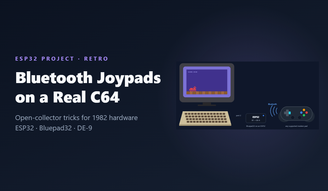
After digging through Fire Ant's machine code in an emulator, the natural next step is playing it the way it was meant to be played: on a real Commodore 64, from the sofa. Original joysticks are wonderful and mostly worn out, and a long cable across the living room is nobody's idea of fun. This project is a small adapter that lets modern Bluetooth game controllers pretend to be a 1980s joystick.
Where the project is today: design stage. This post covers the complete design: electrical interface, parts, wiring, software and test plan. Nothing has been built and tested yet, and the code is a design sketch.
Credit where it is due: Ricardo Quesada's open-source Unijoysticle adapters already do this brilliantly, built on his Bluepad32 library. This design uses Bluepad32 too. The point of building my own is to understand every part of it, and to write it up in detail.
How a C64 joystick actually works
There is no protocol at all. An Atari-style joystick, the kind the C64 uses, is just five switches. Each one connects a signal line to ground when you push that direction or press fire. Inside the computer, each line is pulled up to 5 V and read by one of the two 6526 CIA chips, so a released switch reads as 1 and a pressed one as 0.
| DE-9 pin | Signal | Used here |
|---|---|---|
| 1 | Up | yes |
| 2 | Down | yes |
| 3 | Left | yes |
| 4 | Right | yes |
| 5 | Paddle Y (POT) | no |
| 6 | Fire | yes |
| 7 | +5 V (max 50 mA) | never |
| 8 | Ground | yes |
| 9 | Paddle X (POT) | no |
That simplicity is what makes the adapter possible. To "press" a direction it only has to connect the line to ground, and to release it, it lets go. Pin 7's 5 V supply is far too feeble for an ESP32 with its radio running, so the adapter has its own USB power and shares only ground with the computer.
The one part that matters: open collector
It is tempting to wire ESP32 pins straight to the joystick lines. Don't. The C64 pulls those lines up to 5 V, and the ESP32's pins are 3.3 V parts that are not 5 V tolerant. Even a pin set to "off" would have 5 V pushed into it through the pull-up.
The answer is an open-collector stage on each line: a small NPN transistor whose collector connects to the joystick line and whose emitter goes to ground. When the ESP32 drives the base high, the transistor switches on and pulls the line to about 0 V, which is a press. When the base is low, the transistor is off and the C64's own pull-up holds the line at 5 V, exactly like a released switch. The ESP32 never sees 5 V.
The 100 kΩ resistor holds each transistor firmly off while the ESP32 is booting or unpowered, so the C64 never sees phantom presses. A tidier alternative to ten transistors is a pair of SN74LVC07A chips: hex buffers whose open-drain outputs tolerate 5 V while running from 3.3 V. The catch is that they only come in surface-mount packages.
The hardware
| Part | Why this one | Approx. £ |
|---|---|---|
| ESP32-WROOM-32 development board | The original ESP32 has Classic Bluetooth as well as BLE, which many game controllers need. The newer S3 and C3 are BLE-only. | 6–10 |
| 10 × 2N3904 NPN transistors | One open-collector stage per line: two ports × five lines. | 1–2 |
| 10 × 4.7 kΩ and 10 × 100 kΩ resistors | Base resistor and base pull-down for each stage. | 1–2 |
| 2 × DE-9 female connector and 9-core cable | Or cut up two cheap joystick extension leads. | 6–12 |
| Stripboard or a small two-layer PCB | Stripboard is fine for the first one. | 3–10 |
| LED and 330 Ω resistor | Pairing and port status. | <1 |
| 5 V USB supply | The joystick port cannot power the ESP32. | ~5 |
| 3D-printed enclosure | PETG, with strain relief for both cables. | 2–4 |
All in, roughly £25 to £45.
Wiring
Each ESP32 pin drives one transistor stage, and each stage's collector goes to one pin of a DE-9 socket. The pins chosen avoid the ESP32's strapping pins (0, 2, 5, 12 and 15), the flash pins (6 to 11) and the serial pins that chatter during boot. On WROVER modules, GPIO16 and 17 are used by the PSRAM, so this layout assumes a WROOM.
Software
Bluepad32 does the hard part: pairing with and decoding a long list of controllers, including PlayStation DualShock 4 and DualSense, Xbox Wireless pads on recent firmware, Nintendo Switch Pro and 8BitDo controllers. It runs as an Arduino board package or inside an ESP-IDF project, and hands the application a tidy state for each connected controller.
The adapter's own code is short: turn that state into five "pull this line low" decisions per port, many times a second.
// Design sketch - NOT TESTED ON HARDWARE.
struct Pad   { int axisX, axisY; bool up, down, left, right, a, b, turbo; };  // filled from Bluepad32
struct Lines { bool up, down, left, right, fire; };                          // true = pull line to 0 V

constexpr int DEADZONE = 160;   // of roughly +/-512: about 30 %, ignores stick drift

Lines mapPad(const Pad &p, bool jumpOnB, uint32_t now_ms) {
    Lines l{};
    l.left  = p.left  || p.axisX < -DEADZONE;
    l.right = p.right || p.axisX >  DEADZONE;
    l.up    = p.up    || p.axisY < -DEADZONE || (jumpOnB && p.b);   // stick up = negative Y
    l.down  = p.down  || p.axisY >  DEADZONE;
    if (l.left && l.right) l.left = l.right = false;   // a real joystick cannot do both
    if (l.up && l.down)    l.up = l.down = false;
    const bool turboPhase = (now_ms / 50) % 2;          // 10 Hz auto-fire
    l.fire = p.a || (p.turbo && turboPhase);
    return l;
}

void drivePort(const Lines &l, const uint8_t pins[5]) {
    const bool v[5] = { l.up, l.down, l.left, l.right, l.fire };
    for (int i = 0; i < 5; ++i)
        digitalWrite(pins[i], v[i] ? HIGH : LOW);       // HIGH = transistor on = line at 0 V
}
Mapping choices
| Controller input | C64 effect | Default |
|---|---|---|
| D-pad or left stick | Up, down, left and right (8-way) | on |
| A / Cross | Fire | on |
| B / Circle | Up, for games that jump with up | off |
| X / Square | Auto-fire at 10 Hz | off |
| Select / Share | Swap port 1 and port 2 | button |
| Second controller | Player 2 on the other port | auto |
Opposite directions pressed together are cancelled, because a real joystick physically cannot do that and some games behave strangely if they see it. The stick has a generous dead zone, so a slightly worn thumbstick does not make a character creep across the screen.
Latency
The C64 reads the joystick port whenever the game asks, typically once per frame (50 times a second on a UK PAL machine), and there is no handshake to slow anything down. The only added delay is Bluetooth itself, plus microseconds of transistor switching. That will be measured rather than assumed, by filming the controller and the screen together with a high-frame-rate phone camera.
Testing plan
- Bench test with a multimeter. With the adapter powered but not plugged in, fit a 10 kΩ resistor from each line to a 5 V supply to mimic the C64. Released should read 5 V; pressed should read under 0.2 V.
- Connect with the C64 switched off. The CIA chips are precious and do not like hot-plugging.
- Run a BASIC test. This prints the state of port 2 continuously:
10 PRINT PEEK(56320) AND 31
20 GOTO 10| Action | Value printed | Bit |
|---|---|---|
| Nothing pressed | 31 | — |
| Up | 30 | 0 |
| Down | 29 | 1 |
| Left | 27 | 2 |
| Right | 23 | 3 |
| Fire | 15 | 4 |
Address 56320 ($DC00) is port 2 and 56321 ($DC01) is port 1. Each direction clears its own bit, so diagonals and fire combine predictably: up and fire together reads 14. After that comes the real test, a long session with a few joystick-heavy favourites.
Risks
- Port damage: the biggest risk is to the C64, not the adapter. Connect only with the power off, and keep the ground connection solid.
- Controller quirks: some pads need particular pairing steps or firmware; Bluepad32's documentation lists what is supported.
- Interference: a crowded 2.4 GHz living room can add latency spikes, so the test plan includes a busy-evening check.
What's next
A stripboard prototype first, checked with the multimeter routine above, then a small PCB that plugs straight onto the side of the machine. Later, the POT lines could carry a second fire button, which a few games support, and the same board could serve an Amiga or an Atari with a different cable.
For more ESP32 design write-ups, see my ESP32-S3 vehicle computer.
Related articles
 Retro Games & Reverse Engineering
Cracking Fire Ant: Reverse Engineering a Commodore 64 Game with an AI Pair-Programmer
How a 17 KB Commodore 64 game gave up its secrets: infinite lives in three bytes, a level editor, a cheat key, and a short list of humbling bugs along the way.
- Electronics & ESP32
Building a Satellite GPS Tracker: from a bare ESP32 to a live web dashboard
A small, self-contained ESP32 GPS tracker that logs where it is, what satellites it can see and how healthy its signal is, streaming it all to a live dashboard. No subscription, no cloud, no app.
 Electronics & ESP32
Designing a Battery-Powered E-Paper Market Dashboard with the ESP32-S3
A picture-frame display that shows a watchlist and the day's market moves, wakes every 15 minutes during trading hours and sleeps the rest of the time. Hardware list, wiring, power budget, software design and test plan.